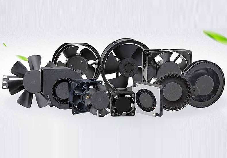


Benefits of Choosing a Higher Voltage DC Cooling Fan
This guide distills the practical benefits of adopting a higher-voltage DC Cooling Fan architecture—efficiency & thermal management, reduced wiring complexity & costs, streamlined system design, and where/how to deploy.

DC Cooling Fan: Enhanced Efficiency & Thermal Management
Reduced heat generation
For a fixed DC Cooling Fan power (P = V × I), raising voltage lowers current, and resistive loss scales with I²R. For example, a 60 W fan draws ~5 A at 12 V, ~2.5 A at 24 V, and ~1.25 A at 48 V—so heating in wires and connectors falls to one-quarter and then one-sixteenth. Cooler harnesses, connectors, and drivers boost overall efficiency and support longer MTBF in dense racks and enclosures.
Higher power-path efficiency
Less current means less copper and contact heating, less voltage sag, and fewer distribution losses. Many BLDC/EC drivers for DC Cooling Fans are also more efficient at 24/48 V because conduction losses are lower for the same airflow output. Net result: a larger share of input power becomes useful CFM and static pressure instead of waste heat.
Higher performance ceiling
Large-frame, high-output DC Cooling Fans often require 24 V or 48 V to sustain speed and torque without pushing cables, terminals, or PCB traces to their current limits. Delivering the same wattage at 12 V can strain wiring and invite voltage drop; stepping up to 24/48 V preserves stability, adds headroom for startup transients and derating (altitude/temperature), and keeps high-performance thermal management reliable as systems scale.

Can a DC Fan Reduce Wiring Complexity and Costs?
Thinner wiring
At the same power, a higher-voltage DC Fan (24 V or 48 V) draws less current, so you can step down wire gauge without sacrificing performance. Smaller cable bundles cut copper cost, reduce harness weight, and open up airflow paths—especially in tight racks and raceways—making the layout easier to route and cool. For reference, a 60 W load drops from ~5 A at 12 V to ~2.5 A at 24 V, often enabling a move from AWG20 to AWG24. Lower I²R heating also extends jacket life and helps avoid hot spots where bundles run near heat-sensitive components.
Smaller connectors and PCB traces
With lower current, a DC Fan lets you use smaller terminals and housings, and narrow PCB traces while staying within temperature-rise limits. That frees board area near the fan header, trims connector bulk, and simplifies mechanical packaging. Reduced contact heating improves long-term reliability at the power jack and headers. In practice, you can migrate from high-current connector families to compact signal-power hybrids for better panel density; on the PCB, shorter/narrower copper clears space for sensors or control logic while remaining within IPC-2152 guidance.
Lower voltage drop on long runs
Voltage drop scales with current (V_drop = I × R). Moving a DC Fan to 24 V or 48 V slashes the percentage drop over long leads, so the fan sees closer to its rated voltage and holds commanded RPM, CFM, and static pressure. Example: with a 0.1 Ω round-trip harness, 5 A at 12 V loses 0.5 V (~4.2%), while 2.5 A at 24 V loses 0.25 V (~1.0%). The extra margin can reduce the need for remote sense wiring, improve cold-start reliability, and keep control signals (PWM/tach) clean under varying load.

How Do DC Cooling Fans Streamline System Design?
Easier power-supply selection
Higher-voltage DC Cooling Fans (24 V/48 V) deliver the same wattage with less current, so the PSU doesn’t need oversized headroom just to ride through spin-up. Most EC/BLDC fan drivers soft-start, further trimming inrush and simplifying fuse/eFuse and cable specs. The lower current widens your qualifying PSU list and lets supplies operate closer to their peak-efficiency window instead of the low-voltage/high-current corner. Ride-through improves as well: with a lighter load, the same input capacitance spans longer disturbances and multi-rail load sharing stays cleaner. Net effect—smaller, cooler, more efficient supplies and a less stressed power chain for the DC Fan network.
Aligned with industry standards
Telecom and data-center platforms commonly standardize on 48 V distribution (within SELV ≤ 60 Vdc). Selecting 48 V DC Cooling Fans drops straight into that ecosystem—busbars, hot-swap PSUs, OR-ing/FET eFuses, and PMBus shelf monitoring are mature and widely available—reducing integration effort and speeding compliance. Point-of-load converters, harness hardware, and test procedures are off-the-shelf, and control interfaces (PWM, tach, fault) remain the same, so you gain 48 V efficiency benefits without reworking fan control logic.
Better scalability
As thermal demand grows, moving from 12 V to 24/48 V keeps current in check, cabling cool, and voltage drop small—making it easier to add higher-power DC Cooling Fans or extra modules without re-looming harnesses or upsizing connectors. For example, a 240 W fan bank pulls ~20 A at 12 V, ~10 A at 24 V, and ~5 A at 48 V, freeing fuse capacity and headroom for future expansion. You also gain margin for transients (spin-up, altitude/temperature derating) and can segment airflow zones (N+1 fan trays, independent rails) while keeping the cabinet’s power architecture stable as you scale.

Cooling fan Typical applications & implementation
Typical applications. DC Cooling Fans are well-suited to high-density servers and data centers (fan trays, rear-door heat exchangers), telecom cabinets built around 48-V backplanes, and industrial, high-power air-cooled gear such as drives, inverters, and sealed control boxes. These environments share high thermal density and higher-voltage rails; running fans at 24/48 V lowers current, which shrinks harnesses, eases routing, improves internal airflow, and keeps control/telemetry predictable—ultimately enabling higher rack density and simpler service.
Implementation notes. To capture those gains in practice, size the fan to the heat load and the real system curve, then compute current at the chosen voltage (I = P/V) to select wire gauge, over-current protection, and connector families. Model round-trip resistance to estimate voltage drop across long leads and multiple connectors so the fan actually sees its rated voltage. Verify rail compatibility (48 V or 24 V with point-of-load conversion where needed) and align control/telemetry—PWM or 0–10 V speed input, tach/FG feedback, and fault/alarm lines. Before release, validate soft-start/inrush, EMI and grounding, and the integrity of the airflow path and seals; document pinouts and spares. Finally, confirm target CFM and static pressure in the enclosure—using ΔP and temperature mapping—not just on a bench.
Conclusion
If you’re pushing higher airflow or static pressure, running long harnesses, or standardizing on telecom/data-center rails, a 24 V/48 V DC Cooling Fan is usually the smarter choice. You’ll waste less energy as heat, simplify cabling and PSUs, and gain headroom for growth.