





How Chassis Fan Walls Cool Passive Server GPUs
Passive server GPUs do not cool themselves. They rely on a chassis fan wall to push air through large heatsinks that have no onboard fans. This design allows data centers to pack more accelerators into a single chassis, but it also makes airflow direction, static pressure and air-shroud sealing critical.
A desktop graphics card can use its own fans to pull air directly through the heatsink. A passive data-center GPU removes those fans and instead depends on the server to move air from front to rear. The chassis must therefore provide enough pressure and enough control to keep every GPU within its thermal limits under continuous AI, inference or HPC workloads.
This article explains how a chassis fan wall cools passive GPUs, why static pressure matters more than free-air CFM, how air shrouds prevent bypass, and what to test before trusting a new configuration.
Key Takeaways
- Passive server GPUs use large heatsinks without onboard fans and depend entirely on chassis airflow.
- The chassis fan wall must generate enough static pressure to overcome dense GPU heatsinks and restrictive ducts.
- Air shrouds and blanking panels force air through the GPU fins instead of letting it bypass around the card.
- Required airflow rises quickly as inlet temperature increases and system resistance grows.
- Fan selection should use the full P–Q curve and be verified by sustained load testing in the actual chassis.
What Is a Passive Server GPU?
A passive server GPU is an accelerator card with a heatsink but no integrated fan. Heat moves from the GPU package into the heatsink base and then into the fin stack. Forced air supplied by the server carries that heat out of the chassis.
Removing the onboard fan lets manufacturers devote more space to the heatsink, which can improve cooling capacity and allow denser accelerator installations. A single server may hold four, eight or more passive GPUs while maintaining a uniform front-to-rear airflow path.
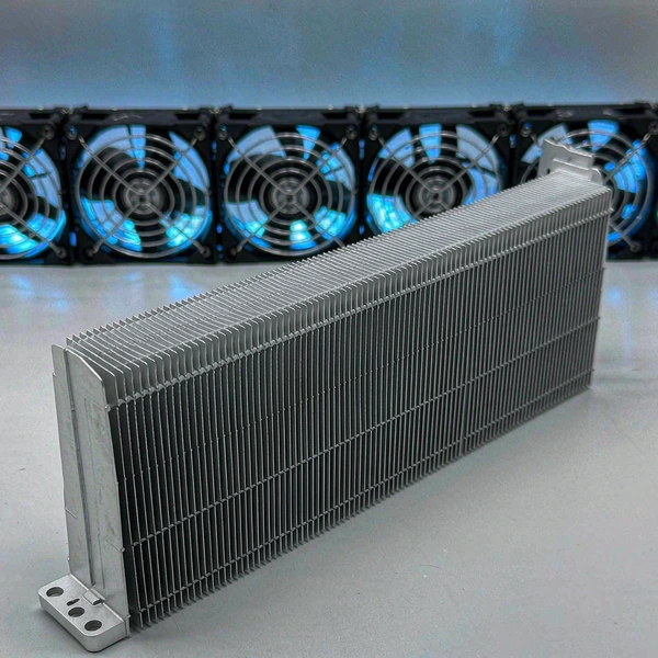
The trade-off is that a passive GPU cannot operate independently. Installing one in a workstation or server that does not supply the correct airflow can cause thermal throttling even when the PCIe slot and power connection are compatible. Electrical fit does not guarantee thermal fit.
How a GPU Server Fan Wall Works
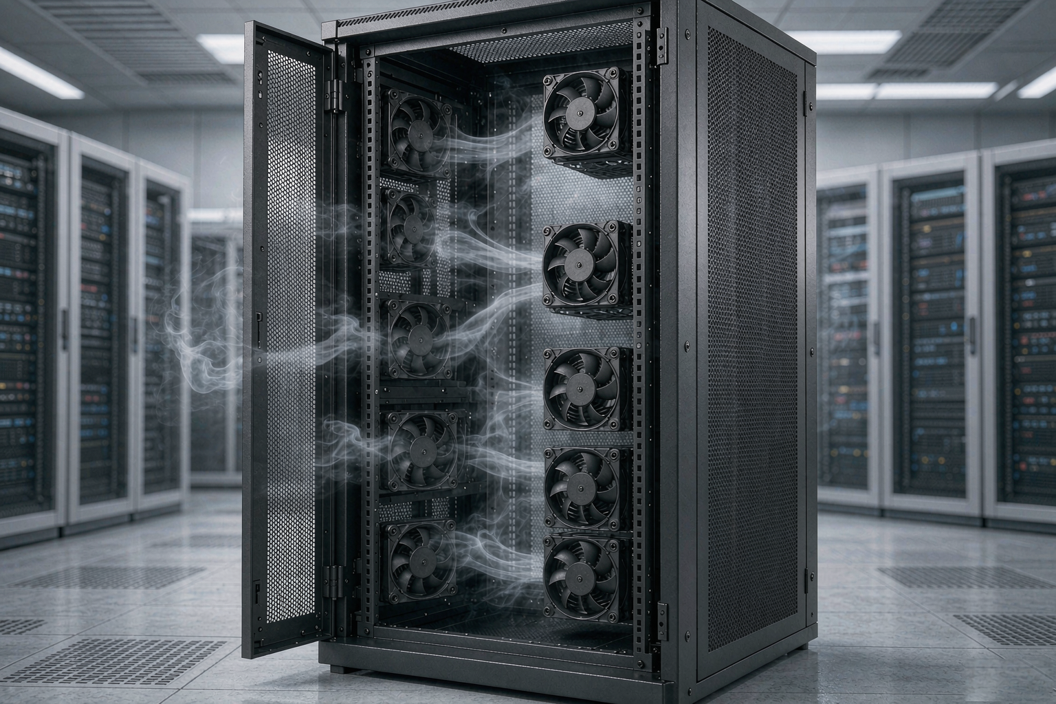
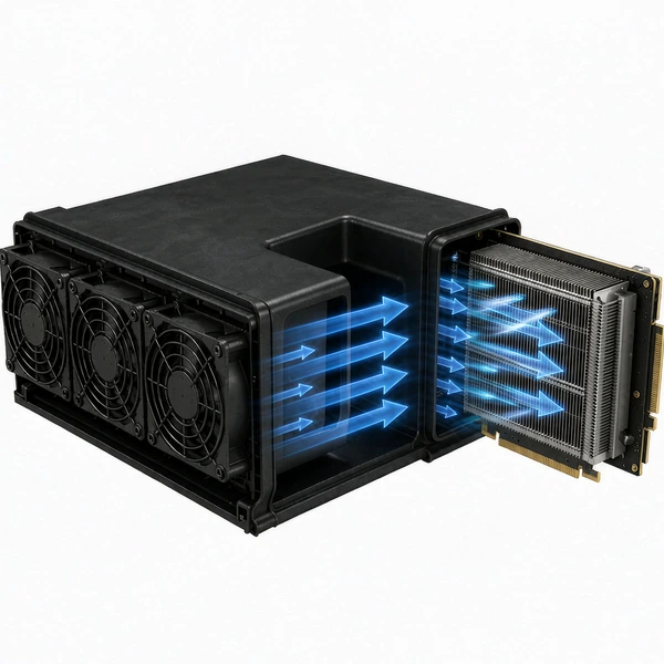
A GPU server fan wall is normally positioned between the front intake and the computing area. It contains several compact, high-speed axial fans arranged across most of the chassis width.
The fans pull cool air through the front intake and create a pressure difference that forces air through the system. Pressurized air moves through processor heatsinks, memory, voltage regulators and the passive GPU heatsinks before exiting at the rear.
A simplified airflow path looks like this: Cold aisle → Front intake → Chassis fan wall → Air shroud → Passive GPU heatsinks → Rear exhaust → Hot aisle.
The fan wall cools more than just GPUs. Processors, memory, storage, network adapters and power components may all share the same airflow. The chassis must divide the air among these thermal zones so that one component does not starve another.
Fan location, GPU spacing and air-shroud geometry must therefore be designed together. Adding powerful fans will not help if the air is not directed through the heat-producing components.
How Much Airflow Does a Passive GPU Need?
There is no single CFM value that works for every passive GPU. Required airflow depends on GPU power, heatsink resistance, inlet temperature and how much air bypasses the card.
Lower-power accelerators may need only moderate, well-directed airflow. High-power GPUs with dense fin stacks need substantially more air and pressure. Installing several cards increases both total heat load and total system resistance at the same time.
Inlet temperature is especially important. As intake air becomes warmer, the temperature difference between air and heatsink falls, so more airflow is needed to remove the same amount of heat.
Published qualification data for the NVIDIA RTX PRO 6000 Blackwell Server Edition shows how minimum qualified airflow rises with inlet temperature:
| GPU heatsink inlet temperature | Minimum qualified airflow |
|---|---|
| 25°C | 43 CFM |
| 30°C | 51 CFM |
| 35°C | 65 CFM |
| 40°C | 84 CFM |
| 45°C | 125 CFM |
These numbers apply to a specific GPU under defined test conditions and should not be treated as a universal specification. They do show why a cooling design that works at 25°C may become inadequate at 40°C, and why hot exhaust recirculation can cause GPU cooling problems even when the fans are running normally.
Ducted GPU heatsinks depend on high-static-pressure DC cooling fans to push air through dense fins where open-frame airflow loses direction.
Why Static Pressure Matters More Than Maximum CFM
Maximum airflow is normally measured in free air with almost no resistance. A server is much more restrictive.
Air must pass through front grilles, storage cages, cables, air shrouds, densely packed heatsinks and rear exhaust openings. Every obstruction creates a pressure loss and reduces the airflow the fan can actually deliver.
A high pressure server fan is designed to maintain useful airflow under resistance. This is essential for passive GPU cooling because the closely spaced heatsink fins form long, narrow channels.
Air naturally follows the easiest path. If an open space above or beside the GPU is less restrictive than the fin channels, much of the airflow may bypass the card. The server can appear to move a large volume of air while the airflow through the GPU itself remains inadequate.
| Fan characteristic | What it indicates | Importance in GPU servers |
|---|---|---|
| Free-air CFM | Maximum airflow with minimal resistance | Useful for initial comparison only |
| Static pressure | Ability to overcome airflow resistance | Critical for dense heatsinks and ducts |
| P–Q curve | Airflow at different pressures | Shows the real operating point |
| Fan depth | Space for motor and impeller | Thicker fans often produce more pressure |
| PWM and FG | Speed control and feedback | Supports system thermal management |
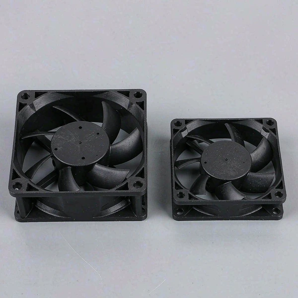
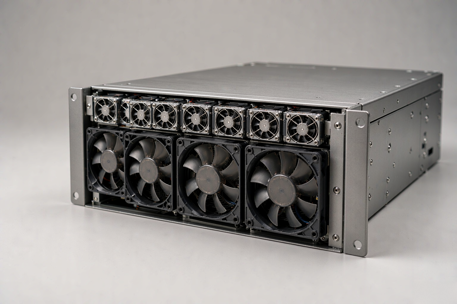
Dense servers commonly use thick, high-speed DC axial fans. A deeper frame can accommodate a stronger motor and impeller, allowing the fan to maintain airflow through restrictive paths. Counter-rotating fans may be used when very high pressure is needed within a limited area.
How Air Shrouds Prevent Airflow Bypass
A powerful fan wall cannot cool a passive GPU if air escapes through easier routes. Air shrouds, ducts, seals and blanking panels are used to control where the airflow travels.
An air shroud forms a sealed channel from the fan wall to the computing components. It blocks open spaces around the GPUs and forces pressurized air toward the heatsink inlets. Blanking panels close unused PCIe positions, while internal baffles can divide the chassis into separate thermal zones.
These parts are essential for passive GPU heatsink cooling. If a shroud is missing or incorrectly installed, air may flow around the GPU instead of through it. Running a server with the cover removed can cause the same problem by disrupting the intended pressure zones.
Heatsink orientation must also match the chassis airflow direction. Air should enter the correct side of the GPU, pass through the full fin structure and exit toward the rear. Some passive cards support more than one airflow direction, but the air must still travel along the heatsink channels.
Cooling Multiple GPUs with One Fan Wall
In a multi-GPU server, accelerators are normally arranged with their heatsink channels aligned to the front-to-rear airflow. One fan wall then creates the pressure needed to move air through several GPU heatsinks at the same time.
The airflow may not be distributed equally. GPU position, cable routing and nearby components change the resistance of each path. Identical cards running the same workload can therefore operate at different temperatures.
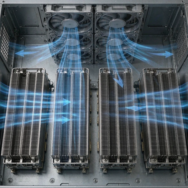
A well-designed chassis fan wall must prevent too much air from flowing through low-resistance openings while other GPUs receive insufficient cooling. Fan position, shroud shape, slot spacing and exhaust resistance all affect the final distribution.
As GPU density increases, the problem becomes harder. More accelerators create more heat, while narrower spaces and additional heatsinks increase resistance. The number of available PCIe slots does not represent the number of GPUs the server can cool.
Electrical capacity, power capacity and thermal capacity must be evaluated separately. A configuration should be validated with the intended GPU quantity rather than assuming that a design for one card will scale directly to eight cards.
Fan Redundancy and Dynamic Speed Control
AI and HPC applications can keep GPUs near full load for many hours. If one fan stops during a sustained workload, component temperatures can rise quickly.
GPU servers commonly use several independent fan modules so that cooling can tolerate a designated fan failure. When a failure occurs, the remaining fans increase speed to preserve adequate airflow until the damaged module is replaced.
Redundancy must be included in the original thermal calculation. If every fan has to run at maximum speed for the server to stay within limits, the system has almost no failure margin. The design should also account for higher inlet temperatures, dust and fan aging.
Modern servers use temperature sensors and a management controller to adjust fan speed dynamically. During lighter workloads the fans can run more slowly to reduce energy and noise. As GPU or inlet temperature rises, the controller raises the PWM duty cycle.
This is one reason an original server fan should not be replaced solely on size and voltage. The replacement fan’s pressure performance, PWM response, tachometer signal and starting current must remain compatible with the server controller.
Selecting YCCFAN Products for GPU Server Cooling
Server GPU fan selection should begin with the thermal and airflow requirements of the complete chassis. Maximum CFM and maximum static pressure provide useful reference points, but neither value represents the actual operating point.
Engineers need to estimate or measure system resistance and compare it with the fan’s P–Q curve. The selected model should deliver enough airflow at that resistance while retaining additional capacity for warmer inlet air and fan-failure conditions.
YCCFAN provides DC cooling fans for servers, communication equipment and other high-density electronics. For passive GPU applications, fan selection can be evaluated by installation size, target airflow, required static pressure, working voltage and control interface.
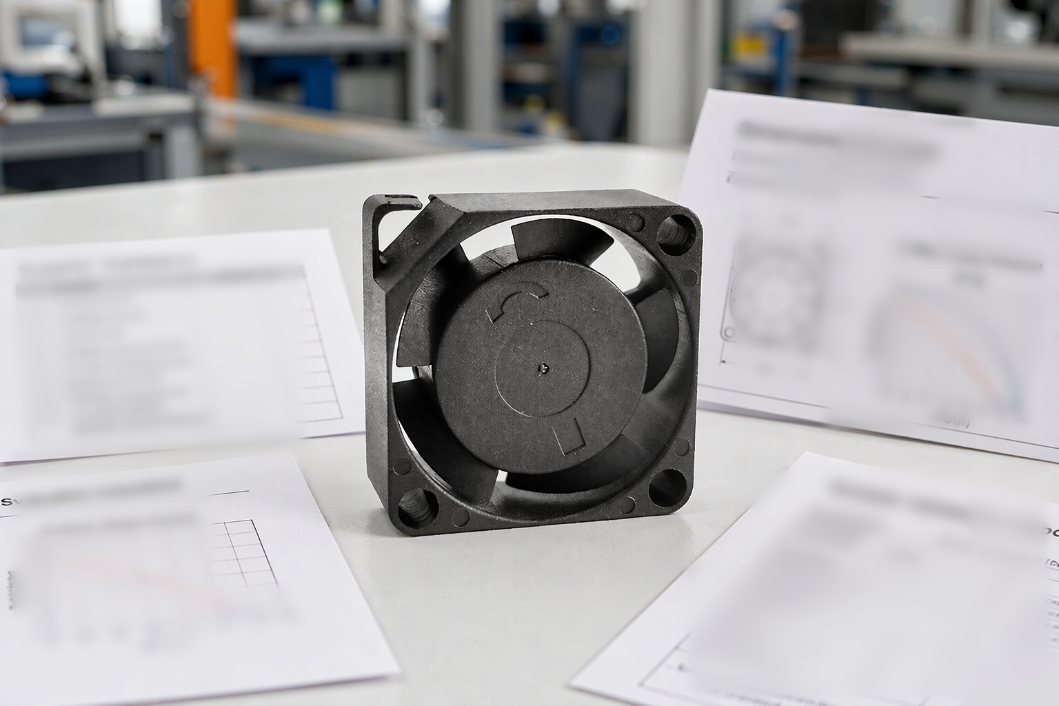
Where a compact fan must force air through dense heatsinks and restrictive ducts, a deep-frame high-pressure design may be suitable. The YCCFAN DC4028G, for example, uses a 40 × 40 × 28 mm frame and is designed for high-resistance cooling paths. Different speed versions offer different combinations of airflow, pressure, power and noise.
For applications that allow greater installation depth and need more pressure, the YCCFAN DC4056G uses a 40 × 40 × 56 mm structure. It is intended for demanding forced-air paths with dense fins, ducts, filters or restricted vents.
These models should be treated as engineering candidates rather than universal GPU cooling solutions. The correct fan depends on the resistance of the complete airflow path and the air required by each GPU. A fan with extremely high static pressure may add unnecessary power and noise if the system resistance is relatively low.
YCCFAN fan configurations can also include PWM speed control, FG speed feedback, RD alarm output, automatic restart and locked-rotor protection according to project needs. These functions let the fans work with the server’s thermal controller instead of running at one fixed speed.
Testing the Cooling System in the Actual Chassis
Calculations and fan specifications should always be followed by testing in the real server. Small differences in grille design, cable placement, air-shroud sealing and GPU position can significantly change how much air reaches each card.
Testing should use the intended number of GPUs and a sustained computational workload. Observe GPU temperature, operating frequency, thermal-throttling status and fan PWM levels. Temperature differences among GPUs can reveal uneven airflow distribution.
The highest expected inlet temperature should also be tested. As inlet air becomes warmer, the server needs more airflow to maintain the same GPU temperature. A system verified only in a cool room may not remain stable in a fully loaded rack.
Where fan redundancy is required, cooling performance should be evaluated with one designated fan unavailable, using an approved and safe test procedure. The remaining fans must maintain sufficient airflow without pushing the GPUs beyond their operating limits.
Diagnosing Passive GPU Overheating
Insufficient fan capacity is only one possible cause of passive GPU overheating. A missing blanking panel, damaged seal or incorrectly installed air shroud can allow air to bypass the heatsink.
Dust at the front intake or between the heatsink fins increases resistance over time. Poorly routed cables may obstruct a fan module outlet. A fan may also continue rotating while operating below its required speed, which makes tachometer monitoring important.
Card position provides another diagnostic clue. If every GPU is hot, the problem may be total airflow, inlet temperature or rack-level hot-air recirculation. If one GPU is consistently hotter, the problem is more likely its slot, nearby obstructions or a local shroud leak.
Thermal throttling is a protective response, not the original fault. Users may first notice reduced or inconsistent AI performance before recognizing an airflow problem. Temperature, clock and fan data should be reviewed together.
Final Thoughts
Passive server GPUs do not operate without fans. Their cooling is moved from each individual card to a centralized chassis fan wall.
Reliable GPU server cooling requires sufficient airflow at the actual system pressure. High-static-pressure fans help overcome restrictive heatsinks, while air shrouds and blanking panels ensure that air passes through the GPUs instead of escaping around them.
GPU power, inlet temperature, card density and chassis resistance all influence the final airflow requirement. This is why one CFM value cannot be applied to every passive GPU or server configuration.
YCCFAN high-pressure DC fans can support the development of server fan walls and other ducted cooling systems when their P–Q performance, electrical controls and installation dimensions match the application. Final selection should always be verified through sustained load testing in the complete chassis.
The key question is not how much air a fan can move in open space. It is how much controlled airflow reaches each passive GPU after the resistance and leakage of the entire server are considered.
When the fans, ducts, heatsinks and thermal controls are correctly matched, one chassis fan wall can cool multiple passive GPUs while supporting high compute density, fan redundancy and stable operation under continuous AI workloads.
FAQ
Can a Passive GPU Work Without a Chassis Fan Wall?
No. A passive GPU has no onboard fan. It depends on the chassis to provide forced airflow through the heatsink. Without a suitable fan wall, duct and pressure, the GPU will overheat.
Why Does Maximum CFM Not Guarantee GPU Cooling?
Maximum CFM is measured in free air with almost no resistance. Inside a server, air must pass through grilles, shrouds and dense heatsink fins. A fan with lower free-air CFM but higher static pressure may deliver more useful airflow through the GPU than a high-CFM fan that cannot overcome the resistance.
How Does Inlet Temperature Affect GPU Cooling?
Warmer intake air reduces the temperature difference between the heatsink and the air, so more airflow is needed to remove the same amount of heat. A design that works at 25°C may fail at 40°C if the fans and pressure cannot scale accordingly.
What Happens When One Fan Fails in a GPU Server?
Most GPU servers use redundant fan modules. If one fan fails, the remaining fans typically increase speed to maintain cooling until the module is replaced. If the system was already running at maximum speed with all fans, there is little margin left for a failure.
Can I Install a Passive GPU in a Workstation?
Only if the workstation can reproduce the forced-air conditions the GPU expects. A typical tower case circulates air through a large open interior, which is not the same as concentrated high-pressure airflow through the GPU heatsink. A custom sealed duct and high-static-pressure fan may be needed.
Compare DC cooling fans for GPU servers and match pressure head to your duct design.