





30mm DC Cooling Fans for Compact Electronics: Pressure, Size and Integration
In compact electronic equipment, cooling fan selection often begins with a mechanical limitation rather than a preferred airflow specification. A designer may have only 30mm of available width, very little clearance above the PCB, and a narrow path for warm air to leave the enclosure.
A 30mm fan can fit into this type of design, but physical compatibility does not guarantee effective cooling. Fan thickness, airflow resistance, voltage, speed, and the position of nearby components all affect its installed performance.
For OEM engineers developing embedded controllers, communication modules, compact power supplies, and other space-constrained electronics, the objective is to select a 30mm DC cooling fan that fits the enclosure and delivers sufficient airflow at the actual system operating point.
Quick Answer
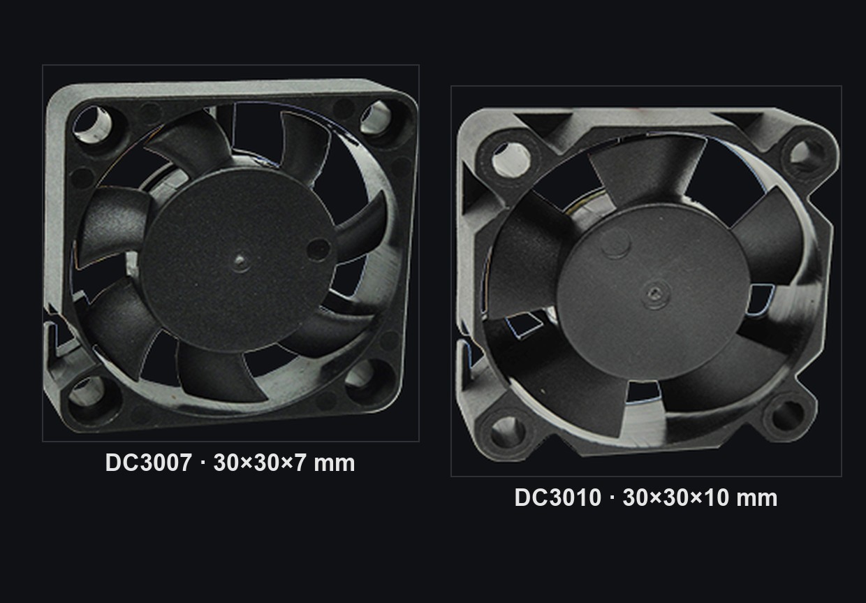
Choose a 30mm DC cooling fan by checking available mounting depth, required voltage, airflow-path resistance, and acceptable noise. A slim 30×30×7mm model suits shallow enclosures, while a 30×30×10mm model may offer greater pressure capability. Verify thermal performance after installation rather than relying on maximum CFM alone.
Key Takeaways
- A 30mm frame specifies fan width and height, but installation depth can determine whether the fan fits.
- The difference between 7mm and 10mm thickness can affect available fan configurations and cooling performance.
- Static pressure becomes especially important when air must pass through narrow vents, dense PCB components, or restricted outlets.
- A 5V, 12V, or 24V fan must be selected for the equipment's electrical architecture and required performance.
- Final approval should depend on measured component temperatures and installed airflow behavior, not catalog maximum values.
Why Cooling a Compact Electronic Enclosure Is Difficult
In a larger enclosure, engineers may have room to separate heat-generating components, install a larger heatsink, or create a relatively open airflow path. Compact devices rarely provide that flexibility.
A power converter, processor, communication chip, or voltage regulator may generate heat within a small PCB area. Connectors, cables, shielding structures, and enclosure walls can restrict the movement of air around those components.
As a result, the problem is not always that the fan produces too little airflow in open space. It may be that the installed system prevents the fan from delivering enough air to the locations where cooling is needed.
Three design constraints commonly appear together.
Limited mounting depth. A fan that fits the available width and height may still interfere with a heatsink, PCB-mounted connector, enclosure wall, or internal cable once its thickness is considered.
Restricted airflow paths. Small ventilation openings and closely arranged components introduce pressure losses. As resistance increases, the operating airflow can fall below the fan's maximum advertised CFM.
Concentrated heat sources. A small airflow stream may bypass the hottest component, producing acceptable general enclosure ventilation but insufficient cooling at a critical location.
A successful cooling layout therefore needs a continuous path for cooler air to enter, pass the relevant heat sources, and leave the equipment without excessive recirculation.
30×30×7mm or 30×30×10mm: Which Fan Fits the Design?
Once the 30mm frame size has been established, fan thickness is often the next critical decision.
A 30×30×7mm fan occupies less depth than a 30×30×10mm fan. That 3mm difference may appear small, but it can determine whether the enclosure closes properly or whether sufficient clearance remains around the fan intake.
However, thinner is not automatically better. A design with more available depth may benefit from a fan configuration offering higher pressure capability or a different airflow-noise balance.
The decision should begin with the actual available space and cooling requirements.
Comparing Two YCCFAN 30mm DC Fan Platforms
| Specification | DC3007 | DC3010 |
|---|---|---|
| Frame dimensions | 30×30×7mm | 30×30×10mm |
| Available rated voltages | 5V, 12V | 5V, 12V, 24V |
| Maximum published airflow | 3.64 CFM | 4.56 CFM |
| Maximum published static pressure | 5.21 mmH₂O | 8.84 mmH₂O |
| Maximum listed speed | 11,000 RPM | 13,000 RPM |
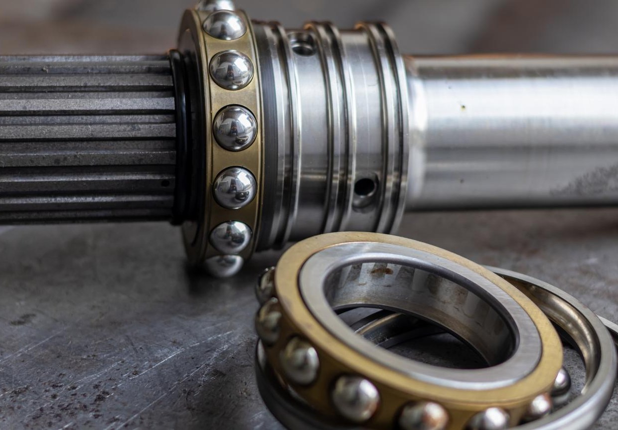
| Bearing options | CycleSeal | CycleSeal or ball bearing |
| Primary selection consideration | Low-profile mechanical integration | Additional voltage and pressure-performance options |
These are family-level published maximum specifications. They do not describe a single shared operating point or guarantee a performance advantage in every enclosure.
For a shallow PCB enclosure where a 10mm fan would interfere with internal components, the DC3007 may be the appropriate starting point. Its 7mm depth can make the mechanical integration feasible without redesigning the housing.
Where a 10mm fan fits and the airflow path is more restrictive, the DC3010 provides additional performance configurations worth evaluating. It also includes 24V versions, which may better match equipment designed around a 24V supply.
The deciding factor is not simply which fan has the higher maximum pressure. It is whether the selected fan can provide the required airflow through the actual enclosure resistance while meeting the noise and electrical requirements.
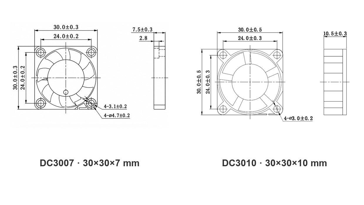
Dimension drawings of the DC3007 (30×30×7 mm) and DC3010 (30×30×10 mm) DC cooling fans
How Much Static Pressure Does a 30mm Fan Need?
Static pressure is particularly important in small cooling systems because airflow restrictions can occupy a large proportion of the available ventilation path.
A fan installed directly against a dense grille, narrow opening, or closely spaced heatsink may experience considerably more resistance than the same fan operating in free air.
The required pressure cannot be determined from the fan diameter alone.
Instead, engineers need to consider the relationship between the fan's pressure–airflow curve, often called a P-Q curve, and the resistance of the equipment's ventilation path.
As airflow increases, the pressure loss through vents, passages, and other obstructions generally increases. The actual operating point occurs where the fan characteristic intersects that system-resistance relationship.
Maximum Airflow Is Not Installed Airflow
Consider a 30mm fan with a published maximum airflow of 4.56 CFM and maximum static pressure of 8.84 mmH₂O.
Those two numbers describe different ends of the fan's performance characteristic. Maximum airflow is generally measured near zero external static pressure, while maximum static pressure occurs near zero airflow.
The fan cannot simultaneously deliver both maximum values.
In a real enclosure, the operating airflow will lie elsewhere on its P-Q curve. Its position depends on how much resistance the device imposes.
The DC3010 family illustrates why choosing only by CFM is incomplete. It provides different speed and voltage configurations with different maximum airflow and pressure ratings, allowing engineers to evaluate alternatives according to their system requirements.
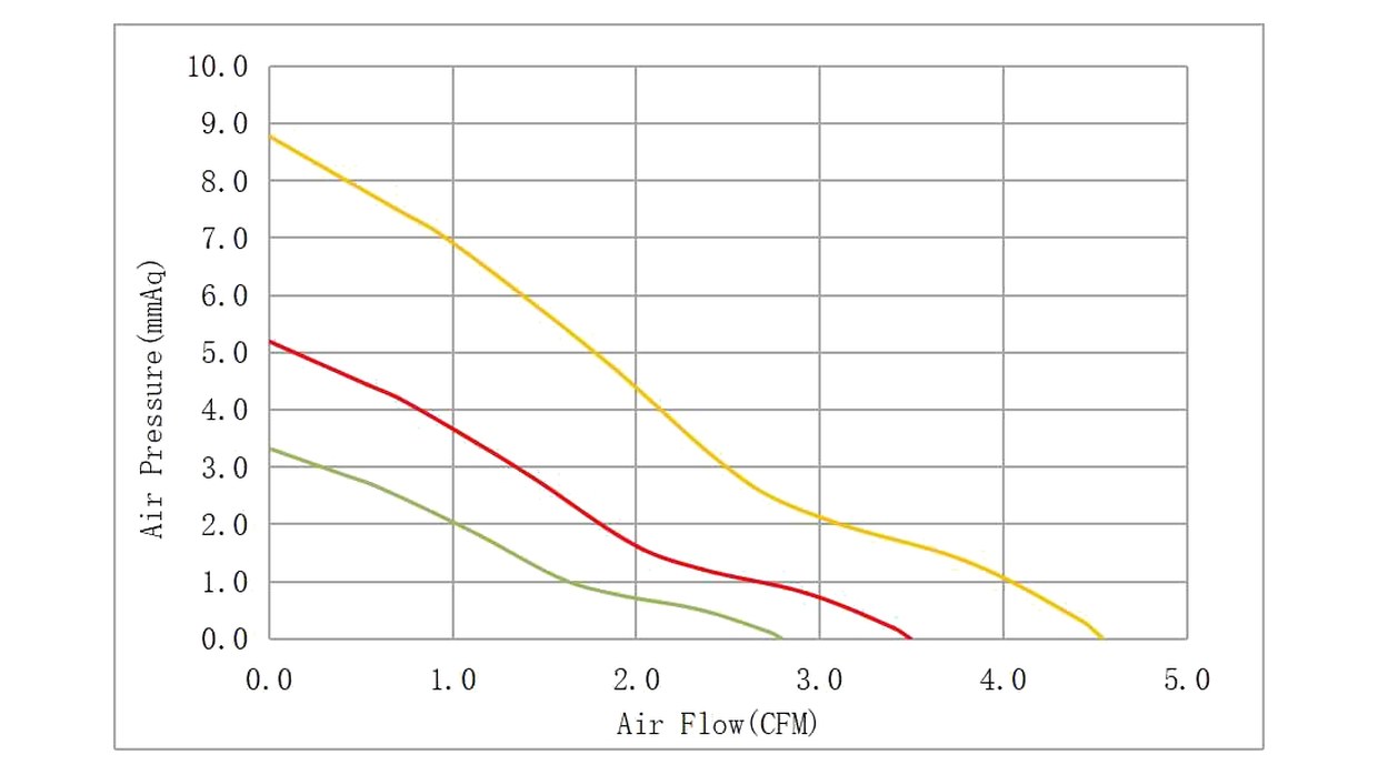
DC3010 DC cooling fan P-Q performance curves (airflow vs. static pressure)
For example, the published 24V versions include:
| DC3010 model | Speed | Maximum airflow | Maximum static pressure | Rated current | Noise |
|---|---|---|---|---|---|
| YDH3010X24 | 13,000 RPM | 4.56 CFM | 8.84 mmH₂O | 0.06 A | 31.63 dBA |
| YDM3010X24 | 10,000 RPM | 3.51 CFM | 5.23 mmH₂O | 0.05 A | 25.36 dBA |
| YDL3010X24 | 8,000 RPM | 2.81 CFM | 3.35 mmH₂O | 0.04 A | 20.00 dBA |
Published values for the corresponding 24V configurations; individual maximum airflow and pressure ratings are not simultaneous.
These figures show the available performance and acoustic trade-offs within one 30mm fan family.
A higher-speed model may offer additional pressure capability but also higher published noise and different power consumption. A lower-speed configuration may be preferable when thermal conditions allow quieter operation.
The appropriate choice depends on the required operating airflow rather than the highest available RPM.
For a more reliable decision, engineers should use the manufacturer's P-Q curves together with representative enclosure testing.
The operating-point principle is also explained in SANYO DENKI's Fan Selection Tutorial, which shows how a fan's P-Q curve intersects the equipment's system-impedance curve.
Selecting 5V, 12V, or 24V for a 30mm Cooling Fan
The correct fan voltage is primarily determined by the equipment's available power supply, electrical design, and required operating characteristics.
It should not be assumed that a 24V fan inherently provides more airflow or better cooling than every 5V or 12V fan.
Fan performance also depends on motor design, rated speed, current, blade geometry, and the exact model configuration.
For example, YCCFAN's DC3010 family includes 5V, 12V, and 24V models. The available speeds and performance values vary by version, so engineers should compare the selected model's actual data rather than assuming all voltage variants behave identically.
When reviewing voltage options, four electrical details are especially important.
Available supply voltage. The fan should match the intended supply rail or a properly designed power-conversion stage. A fan should not be operated outside its specified voltage range.
Operating and startup current. The power system must support the fan during normal running and startup. Catalog rated current alone may not describe every transient condition.
Speed control requirements. Some electronic products need to adjust fan speed according to component temperatures or system operating modes. Control method and signal compatibility must be confirmed for the actual fan configuration.
Fault monitoring. Equipment requiring fan-status detection may need options such as speed feedback or rotation detection, depending on the selected model.
For example, YCCFAN lists optional PWM, FG, RD, auto-restart, and polarity-protection features for the DC3010 family. Their inclusion should be specified for the required model rather than assumed to be standard in every version.
The goal is a stable electrical and thermal integration, not simply selecting the highest available voltage.
Where Should a 30mm Fan Be Installed Inside Compact Electronics?
The effectiveness of a small cooling fan depends strongly on its position relative to the heat source, air inlet, and exhaust.
A fan installed in a mechanically convenient location may not provide the best cooling if its airflow bypasses the components that need it most.
In PCB-based products, engineers should first identify the main heat-generating components and understand how heat is transferred through the board, heatsinks, and surrounding air.
Create a Continuous Airflow Path
A practical airflow layout should provide a sufficiently open inlet, a path across the intended cooling area, and an outlet for heated air.
Placing a fan immediately against an almost solid enclosure wall may restrict the inlet or outlet. Similarly, cables and connectors positioned close to the fan can obstruct airflow and create additional turbulence.
Airflow direction also matters. Depending on the housing design, a fan may be used to introduce cooler air or exhaust heated air. Neither arrangement is automatically superior in every compact device.
The correct configuration is the one that produces acceptable component temperatures under the expected operating conditions.
Avoid Localized Recirculation
In tightly packaged electronics, warm exhaust air can sometimes return directly to the fan inlet through nearby openings or internal gaps.
This recirculation can reduce cooling effectiveness even when the fan is operating at its expected speed.
Mechanical features such as internal partitions, properly positioned vents, and suitable fan placement can help direct air through the intended path.
However, additional ducts and barriers also create pressure resistance. They should be evaluated as part of the complete system rather than added without testing.
Leave Space for Assembly and Service
A 30mm fan installation must accommodate more than the nominal 30×30mm frame.
Engineering drawings should be checked for mounting-hole positions, frame thickness, wire exit direction, connector clearance, and the space required for assembly.
Vibration transfer to the enclosure may also need attention, particularly in devices with thin plastic housings or acoustic requirements.
These mechanical details should be resolved before production tooling or PCB layouts are finalized. A fan that meets thermal specifications but cannot be assembled consistently is not a suitable OEM solution.
Typical Applications for 30mm DC Cooling Fans
A 30mm cooling fan is most useful where active airflow is needed but the enclosure cannot accommodate a larger fan.
The cooling architecture differs depending on the equipment design, so the same fan configuration should not be applied automatically across all applications.
Embedded Control Electronics
Compact controllers and embedded modules may combine processors, power regulators, and communication components in a confined space. A 30mm fan can provide local airflow where passive cooling is insufficient, provided the enclosure has a usable ventilation path.
Communication and Network Modules
Small network terminals and communication modules can contain dense circuit boards and localized heat sources. Designers may prioritize compact installation, reliable airflow, and fan monitoring functions where continuous equipment operation is required.
Compact Power Supplies
Power conversion components may generate concentrated heat near switching devices, transformers, and other electrical components. A 30mm fan can be considered when the cooling path and enclosure size support effective forced-air ventilation.
Low-Profile Display and Control Units
Thin control panels and display modules may have adequate width for a 30mm fan but limited internal depth. In these designs, a 7mm fan configuration can be worth evaluating when a 10mm unit would interfere with neighboring components.
These are representative application scenarios, not guaranteed matches for every enclosure. The selected fan must still satisfy the actual thermal, mechanical, electrical, and acoustic requirements.
How to Validate a 30mm Fan Before OEM Production
The most useful fan validation process begins with the equipment rather than the fan datasheet.
A candidate model should first be screened for dimensions, supply compatibility, airflow, static pressure, and noise. After that, representative samples should be evaluated inside the intended enclosure.
For an OEM project, the following checks can help reveal problems before production approval.
| Validation area | What to measure or confirm | Common issue to identify |
|---|---|---|
| Mechanical fit | Mounting depth, holes, wiring and connector clearance | Fan fits nominal space but conflicts during assembly |
| Component temperatures | Critical component temperatures at representative loads | Local overheating despite fan operation |
| Airflow path | Inlet, exhaust, obstruction and recirculation | Air bypasses the intended heat source |
| Power supply | Startup, operating voltage and current | Unstable startup or insufficient supply capacity |
| Acoustics | Installed noise at intended operating modes | Grille turbulence or enclosure vibration |
| Fan control | Required control and feedback behavior | Incorrect signal interface or speed control |
| Environmental conditions | Operating temperature and expected exposure | Fan operating outside its rated conditions |
When comparing candidate fans, engineers should hold the test conditions as consistent as possible. Changes in enclosure configuration, applied thermal load, ambient temperature, or measurement position can obscure the differences between fan models.
It is also important to avoid selecting a fan solely because it passes a brief room-temperature test. The final design should be evaluated under representative high-load conditions and any other operating scenarios required by the product.
For applications requiring long-term reliability, relevant manufacturer life data and environmental qualifications should also be reviewed.
When Should You Choose a Different Fan Size or Airflow Design?
A 30mm axial fan is not always the right solution, even when it fits physically.
If the equipment requires substantially more airflow than the available 30mm models can provide, increasing the fan's speed may produce unacceptable noise without delivering enough additional installed airflow.
Where mechanical space permits, a larger fan may provide another design option.
Likewise, if the airflow must follow a highly restrictive duct or turn sharply toward a concentrated heat source, a compact centrifugal blower may be worth evaluating. A blower changes the available outlet geometry and pressure–flow characteristics, but its performance must still be checked against the actual system resistance.
There are also situations in which improving heatsink geometry, relocating vents, reducing unnecessary obstructions, or changing the component layout offers more benefit than replacing the fan.
For a new OEM design, these options are easier to evaluate before the enclosure and PCB arrangement are finalized.
The best cooling solution is not necessarily the smallest or fastest fan. It is the combination of enclosure design and air-moving components that maintains acceptable temperatures within the available space, electrical budget, and noise limits.
FAQ
Is a 30mm fan enough to cool an electronic device?
A 30mm fan may be sufficient for a compact electronic device if its installed airflow maintains all critical components within their permitted temperatures. The answer depends on heat generation, enclosure ventilation, airflow resistance, ambient temperature, and fan performance. A thermal test of the complete equipment is needed for confirmation.
What is the difference between a 30×30×7mm and a 30×30×10mm fan?
Both share a nominal 30mm width and height, but they differ in frame depth. The 7mm configuration can fit thinner enclosures, while a 10mm fan may provide different airflow, pressure, voltage, or speed options. Actual differences must be checked using the corresponding model specifications.
Should I choose airflow or static pressure when selecting a 30mm cooling fan?
Both matter. Airflow describes the amount of air moved, while static pressure indicates the fan's ability to work against resistance. In compact devices with narrow vents or dense components, the pressure–airflow curve is more useful than either maximum value by itself.
Can a 24V 30mm fan replace a 12V version?
Not without checking the power system and the exact model specifications. A 24V fan should be operated within its specified voltage range and connected to a compatible supply. Different voltage versions can also have different current, speed, airflow, and control characteristics.
Are high-speed 30mm fans always louder?
Higher rotational speed often increases aerodynamic noise, but actual sound levels also depend on blade design, motor construction, bearing type, and installation conditions. Comparing published dBA values under equivalent test conditions and measuring noise in the finished enclosure provides a better basis for selection.
Can a 30mm DC fan support PWM speed control or fan monitoring?
Some models support optional speed control and monitoring functions. For example, YCCFAN lists PWM, FG, and RD options for certain 30mm fan families. These functions must be confirmed for the exact ordered configuration because they may not be included in every standard model.
Conclusion
Selecting a 30mm DC cooling fan for compact electronics requires a balance between mechanical fit and actual thermal performance.
A slim 7mm model may solve an installation-depth constraint, while a 10mm configuration can provide additional voltage and pressure-performance choices. Neither option should be selected using maximum airflow alone.
The most reliable approach is to evaluate available installation space, airflow-path resistance, supply voltage, noise limits, and critical component temperatures together.
YCCFAN offers compact 30mm axial DC fan configurations for different space and performance requirements, including the DC3007 slim cooling fan and DC3010 high-pressure cooling fan. Browse the full DC cooling fan range for additional sizes and configurations.
For OEM cooling requirements, explore YCCFAN's DC3007 and DC3010 fan options, or contact YCCFAN to discuss mounting dimensions, voltage, thermal conditions, and sample requirements.