





Why Your Blower Fan Delivers Less Airflow After Installation
The blower looked powerful on the datasheet. It may even have moved plenty of air during a bench test. Then you installed it behind a filter, connected a duct, closed the enclosure—and the airflow seemed to disappear.
In many cases, the blower itself has not suddenly become weaker. The installation has changed the pressure conditions under which it operates.
A blower's maximum airflow rating is not a guarantee of the airflow it will deliver inside finished equipment. Once filters, grilles, heat sinks, ducts, bends, narrow openings and internal components are added, the blower must overcome additional resistance. Its real operating condition moves away from the low-resistance end of the performance curve, and blower fan airflow falls.
AMCA describes installation-related losses caused by poor inlet or outlet conditions as system effect. Even a correctly selected fan can perform below catalog expectations when the airflow entering or leaving it is disturbed by the way the system is built. So before replacing the blower with a larger model, determine what actually changed after installation.
First Question: Did the Blower Lose Speed, or Did the System Gain Resistance?
These two problems can feel almost identical at the outlet, but they require very different fixes.
If the blower RPM has fallen, investigate the electrical or control side. Possible causes include:
- supply voltage below the required level
- an unintended PWM command
- a controller limiting fan speed
- incorrect control settings
- unstable power under load
- a blower operating at a lower programmed speed than expected.
If the blower is still running at the expected RPM but airflow has dropped significantly, the more likely problem is blower airflow restriction somewhere in the installed system.
This distinction matters because increasing voltage, changing PWM settings or replacing the motor will not fix an undersized vent or restrictive filter.
Where available, an FG speed signal can be particularly useful during diagnosis because it allows engineers to separate an RPM problem from a system-resistance problem. For example, YCCFAN's DC3010 blower supports optional FG, RD and PWM functions in addition to multiple speed versions.
Normal RPM + low airflow usually points toward the airflow path.
Low RPM + low airflow requires checking the blower drive and control conditions first.
Where Does Blower Fan Airflow Actually Disappear?
Airflow losses rarely come from one mysterious source. They are usually distributed across several restrictions that were not present during the original fan test. A finished system may look mechanically simple while presenting a surprisingly difficult airflow path.
| Installation Symptom | Likely Cause | What to Inspect |
|---|---|---|
| Airflow drops immediately after enclosure assembly | Restricted inlet or outlet | Clearance, vent area, grille |
| Airflow drops after a filter is installed | Filter pressure drop | Filter area, media, loading |
| Airflow is strong at blower outlet but weak farther downstream | Duct or bend losses | Elbows, transitions, duct size |
| Airflow varies after panels are fitted | Internal system resistance | PCB, heat sink, cables |
| Airflow decreases gradually over weeks or months | Filter contamination | Differential pressure, dust |
| RPM is correct but delivered airflow is low | Operating point shifted | P-Q curve and system resistance |
| Airflow reaches the wrong area of the equipment | Bypass or leakage | Gaps, seals, duct routing |
The value of this table is not to identify the fault immediately. It is to help determine where to start isolating the restriction.
1. The Blower Inlet Is Too Close to a Wall or Component
A centrifugal blower needs air to reach its inlet cleanly. If the intake is positioned only a few millimeters from a panel, PCB, battery, cable bundle or internal partition, the blower may be starved before air even reaches the impeller.
The result can be confusing because the blower still sounds fast, the motor still runs, the outlet still produces some air, and there may be no visible obstruction directly inside the inlet. Yet the effective inlet area around the blower may be much smaller than expected.
Poor inlet conditions can also create non-uniform airflow into a centrifugal impeller. Greenheck notes that restricted or unstable inlet flow can create uneven loading and substantial system losses in centrifugal fan installations.
What to check
Temporarily increase the clearance around the inlet without changing anything else. If airflow rises noticeably, the blower probably does not need to be replaced. The surrounding structure needs to be redesigned.
Possible corrections include:
- increasing inlet clearance
- moving cables away from the intake
- enlarging the inlet opening
- using a smoother transition into the blower
- relocating the blower slightly
- removing unnecessary structures immediately upstream.
This is often a better solution than increasing blower RPM and accepting more noise.
2. The Filter Pressure Drop Is Higher Than Expected
Filters are one of the most common reasons a blower performs differently after assembly. A filter does not merely remove dust. It also adds resistance.
The important specification is therefore not just filtration efficiency. Engineers also need to know the filter pressure drop at the intended airflow.
If a filter is too small, too dense or operated above its intended face velocity, the blower may have to produce significantly more pressure to maintain the same CFM. As dust accumulates, the problem can become more severe. Donaldson notes that increasing differential pressure across filtration media can result from accumulated dust adding resistance to airflow.
Immediate airflow loss
If airflow becomes poor as soon as a brand-new filter is installed, investigate:
- filter media resistance
- filter surface area
- filter thickness
- face velocity
- supporting mesh or grille
- sealing geometry around the filter.
Airflow loss over time
If the system performs correctly when new but deteriorates after weeks or months, contamination may be increasing the filter pressure drop. That means a design should not be validated only with a perfectly clean filter.
The real question is: Can the blower still provide acceptable airflow as the filter approaches its normal service condition? Simply specifying a higher-efficiency filter without considering pressure drop can shift the blower to a much lower airflow operating point.
3. An Elbow Is Installed Too Close to the Blower Outlet
This problem is especially easy to create in compact equipment. The blower outlet points in one direction, but the product architecture requires the air to turn almost immediately. A 90-degree elbow is therefore placed directly against the discharge. Mechanically, the layout is convenient. Aerodynamically, it can be expensive.
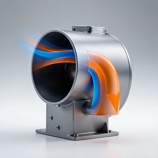
Air leaving a centrifugal fan does not automatically have a perfectly uniform velocity profile. If it is forced into a sharp change of direction before the discharge flow has stabilized, additional losses can occur. AMCA specifically identifies elbows installed too close to a fan outlet as a source of significant airflow loss. Its guidance notes that sufficient straight duct length helps the outlet velocity profile develop before a major turn.
Symptoms may include
- lower airflow than the fan curve predicted
- increased turbulence noise
- uneven airflow after the bend
- unexpected pressure loss
- one duct branch receiving much more air than another.
If packaging space permits, adding a short straight section before the bend can improve conditions. Where space does not permit it, a smoother transition or larger-radius bend may be preferable to simply increasing blower speed.
4. The Duct or Outlet Opening Is Smaller Than the Blower Needs
A common design assumption is: If the blower outlet is small, the connected duct can also be very small. That does not necessarily follow.
Every reduction, transition, grille and narrow passage contributes resistance. A system may contain a blower capable of producing substantial static pressure and still suffer poor airflow because the downstream path is unnecessarily restrictive.
Typical examples include:
- narrow exhaust slots
- small perforated panels
- decorative grilles
- undersized flexible tubing
- abrupt duct reductions
- long narrow channels
- partially blocked outlets.
The important issue is not whether air can physically pass through the opening. It is whether the blower can move the required volume of air through that opening at the resulting pressure.
Static pressure represents the pressure a fan needs to overcome resistance created by the airflow system. Filters, grilles and other impedances are examples of sources of this resistance. A small outlet therefore does not simply make air "come out faster." It can move the blower to a lower-flow region of its performance curve.
5. Internal Components Are Acting Like a Duct System
Electronics designers do not always think of a PCB enclosure as a duct. From the blower's perspective, however, it often is one.
Air may need to move past heat-sink fins, multiple PCBs, transformers, batteries, power modules, cable harnesses, connectors, shields and internal brackets. Each obstruction changes the airflow path.
Several moderate restrictions can combine into a substantial pressure requirement even when no individual component looks particularly problematic. This is one reason centrifugal blower airflow often needs to be evaluated with the actual equipment geometry rather than from a simple free-air test.
Centrifugal blowers are generally selected for applications that need stronger static-pressure capability than open-air axial fan applications. ebm-papst describes centrifugal designs as suitable for producing higher static pressure in restricted airflow systems.
But "higher static pressure" does not mean "unlimited resistance." Every blower still has a performance boundary. As system resistance rises, airflow eventually falls.
6. Air Is Escaping Before It Reaches the Component You Want to Cool
Sometimes the blower is moving enough total air, but the equipment still appears to have an airflow problem. The missing airflow may actually be bypassing the intended cooling path.
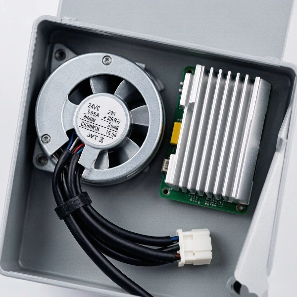
For example, suppose the purpose of the blower is to push air through a dense heat sink. If there is a large open gap beside the heat sink, air may choose that lower-resistance route instead. The blower can therefore be operating normally while only a small portion of its airflow passes through the target component.
This can happen around poorly sealed ducts, heat-sink edges, loose foam seals, gaps between panels, unused ventilation openings, incomplete air guides and gaps around filters.
This type of failure is different from a blower simply producing insufficient CFM. You need to distinguish total blower airflow from useful airflow through the target cooling path.
A higher-output blower may increase total airflow but still leave the hot component inadequately cooled if the bypass path remains easier. Baffles, seals or localized ducting can sometimes produce a larger thermal improvement than installing a more powerful blower.
7. The Original Blower Was Selected from Free-Air CFM Alone
This is the point where the fan itself may genuinely be mismatched to the application. Suppose a blower is advertised with a maximum airflow of 20 CFM. That number does not mean 20 CFM through any filter, duct or heat sink. Maximum airflow occurs near the low-pressure end of the blower performance curve. As resistance increases, the actual airflow moves to another point on that curve.
YCCFAN's existing guide to the DC blower fan curve explains that the real operating point is determined by the intersection between the blower P-Q curve and system resistance curve.
For this article, the important point is not how to read every part of that curve. It is what the curve tells you during troubleshooting: If the installed system requires more static pressure than originally expected, lower airflow may be exactly what the blower performance curve predicts.
In that case, you have two broad options:
- reduce the system resistance; or
- select a blower capable of delivering the required airflow at the higher pressure.
Replacing a blower simply because another model has a larger free-air CFM number may repeat the same mistake.
A Hypothetical Example: Why a 20 CFM Blower May Deliver Much Less in the Product
Consider a hypothetical compact electronic device. During an open bench test, the blower produces close to its advertised high-airflow condition. The production version then adds an intake filter, a protective grille, a compact internal heat sink, a short outlet duct and one sharp 90-degree turn.
None of these components individually looks severe. Together, however, they increase system resistance. Instead of operating near the right-hand, high-airflow portion of its P-Q curve, the blower moves toward a higher-pressure, lower-flow operating point. The measured result might now be substantially below the original free-air airflow.
That does not automatically indicate defective bearings, a weak motor, incorrect fan manufacturing or a false airflow specification. The blower may simply be operating at a completely different point.
If removing the filter increases airflow, the filter contributes meaningful resistance. If removing the outlet elbow improves airflow again, another pressure loss has been identified. If increasing inlet clearance gives another improvement, the restrictions are accumulating. This type of one-variable-at-a-time test is much more informative than immediately ordering a higher-RPM blower.
A Better Way to Troubleshoot Blower Fan Losing Airflow
When a blower fan is losing airflow after installation, avoid changing several things at once. Use an isolation process.
Test A: Verify the electrical operating condition
Measure or confirm:
- supply voltage at the blower
- PWM command, if used
- expected RPM
- control mode
- FG feedback, if available.
If RPM is unexpectedly low, solve that problem first.
Test B: Run the blower with the enclosure open
Compare airflow behavior with the system closed and open. A large improvement after opening the housing strongly suggests that the enclosure is introducing significant resistance or inlet starvation.
Test C: Remove the filter temporarily
This is a diagnostic test—not a permanent recommendation. If airflow rises significantly, investigate the filter's pressure-drop characteristics, surface area and loading condition.
Test D: Remove downstream restrictions one at a time
Test the system with grille removed, duct disconnected, elbow removed and heat-sink channel opened. The component that produces the largest change deserves closer attention.
Test E: Check the inlet independently
Engineers often focus on the outlet and forget that the inlet can be equally important. Give the blower unrestricted inlet access temporarily. If airflow rises, improve inlet geometry before changing the fan.
Test F: Measure pressure where possible
A differential pressure measurement across a filter can help show whether the filter has become a significant restriction. Differential-pressure monitoring is widely used to evaluate changes in filtration resistance.
For more complete engineering validation, system pressure should be compared with the blower's published performance curve.
Don't Automatically Solve Low Airflow by Increasing RPM
Higher speed can increase available airflow and pressure, but it comes with tradeoffs. Depending on the blower and operating point, these may include:
- higher acoustic noise
- greater electrical power consumption
- increased vibration
- tighter control requirements
- possible lifetime implications
- more turbulence through restrictive structures.
More importantly, increasing RPM does not correct poor system geometry. If the inlet is partially blocked or the outlet makes an unnecessarily abrupt turn, redesigning the airflow path may give a better result without increasing fan speed. This is especially relevant when the equipment has strict noise or power limits.
When Is a Higher-Pressure Centrifugal Blower Actually the Right Fix?
There are cases where the airflow path cannot simply be opened. For example:
- the product requires filtration
- the heat sink must remain dense
- packaging limits require narrow channels
- air must be directed through a specific component
- the duct path cannot be shortened
- the enclosure cannot accommodate a large open vent.
Under those conditions, resistance is part of the application rather than a design mistake. That is where blower static pressure becomes an important selection parameter.
YCCFAN's DC blower category includes compact centrifugal blower formats such as B3510, B6012, DC2006, DC2008, DC2507F, DC3007, DC3010 and other sizes intended for different installation requirements.
As one example, the 30 × 30 × 10 mm YCCFAN DC3010 blower includes 5 V and 12 V versions with different speed, airflow and static-pressure ratings. The published specifications also provide characteristic curves rather than only a single maximum CFM value. That is the type of information that matters when matching a blower to a restricted system.
For engineering selection, useful project data should include:
- required airflow at the target component
- estimated or measured pressure resistance
- filter type and pressure drop
- inlet and outlet dimensions
- duct length and bends
- available blower space
- supply voltage
- target RPM or control strategy
- noise limit
- FG, RD or PWM requirements.
This provides a much stronger basis for blower selection than asking only for maximum CFM.
Fix the Restriction Before Blaming the Blower
A blower that delivers less airflow after installation is not necessarily underperforming.
In many cases, the difference between catalog airflow and installed airflow can be traced to what was added around the blower:
filter → grille → inlet clearance → heat sink → duct → bend → outlet
Every element asks the blower to generate pressure. The more resistance the finished system creates, the farther the operating condition moves away from free-air maximum CFM.
A useful troubleshooting sequence is therefore:
verify RPM → isolate restrictions → check inlet → inspect filter → inspect outlet geometry → measure pressure → compare with blower performance.
Only after those checks should you conclude that the blower itself needs to be changed. The objective is not to find the blower with the largest airflow number. It is to build a system in which the selected blower can deliver the airflow that the equipment actually needs.
FAQ
Why does blower airflow decrease when I restrict the outlet?
Restricting the outlet increases the pressure resistance the blower must overcome. As system resistance rises, the operating point moves along the blower's pressure-airflow curve toward lower airflow. A centrifugal blower can usually tolerate more restriction than a low-pressure axial fan, but its airflow will still decline once back pressure increases.
Can a dirty filter reduce blower fan airflow?
Yes. Dust accumulating on a filter increases resistance to airflow and can increase differential pressure across the filter. As that resistance rises, a fixed-speed blower may deliver less airflow through the system. This is why airflow validation should consider not only a clean filter but also realistic filter loading and maintenance conditions.
Does adding a duct always reduce blower airflow?
Not necessarily by the same amount, but a duct system introduces pressure losses that must be considered. Long narrow ducts, abrupt transitions, sharp elbows and poorly positioned outlet fittings can increase those losses. An elbow placed directly at a fan discharge can also create additional system-effect losses. A well-designed duct can therefore perform much better than a short but badly configured one.
How do I know if my blower fan is too small or if the enclosure is too restrictive?
Start by confirming blower voltage, control signal and RPM. Then remove restrictions one at a time. If airflow improves dramatically after removing a filter, grille, bend or enclosure panel, system resistance is a major contributor. If the airflow requirement still cannot be achieved after the airflow path is reasonably optimized, compare the required airflow and static pressure with the blower's performance curve. If the target operating point lies outside the blower's usable range, a different blower is required.