



How to Choose Server Rack Cooling Fans for Effective Airflow
The right server rack cooling fans are not simply the models with the highest free-air CFM. Effective rack cooling begins with a defined airflow path, controlled openings and a realistic estimate of system resistance. The fan must then deliver enough airflow at the operating point created by filters, doors, cable bundles, drive bays, heat sinks and ducts.
For most rack-mounted IT equipment, the intended direction is front to rear. A successful design supplies cool air to equipment inlets, prevents hot exhaust from returning to those inlets and verifies temperatures under the actual rack load. Fan specifications narrow the candidates, but instrumented testing confirms the final choice.
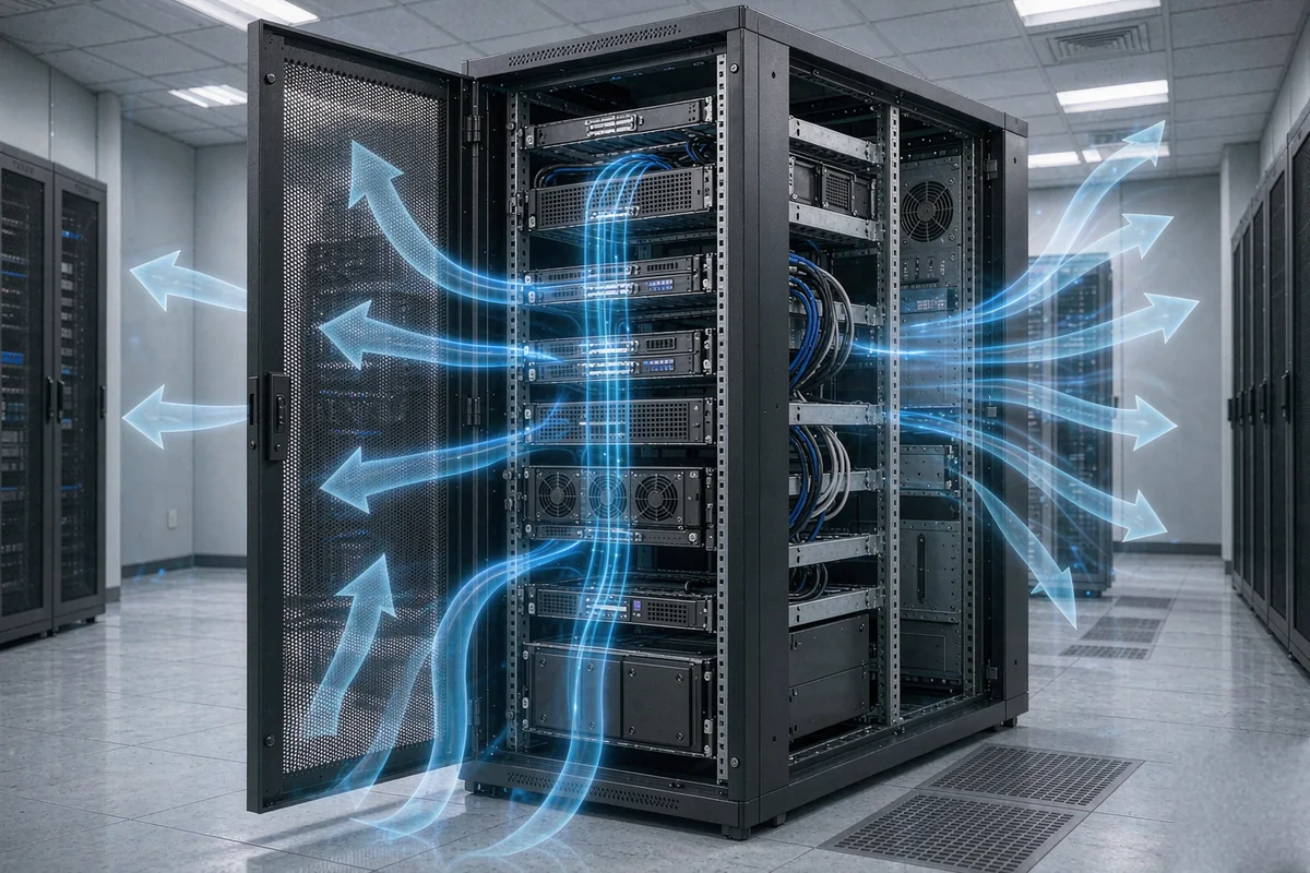
A defined front-to-rear airflow path is the basis of server rack cooling: cool air reaches the equipment inlets and hot exhaust leaves at the rear without recirculating.
Plan the Airflow Path for Server Rack Cooling
Before comparing fan models, draw the path that air must follow. Mark the cool-air entry, each heat-producing component or device, the main restrictions and the exhaust route. At facility level, data center airflow guidance emphasizes separating cool supply air from hot return air and reducing bypass and recirculation. Published system-level airflow testing also shows that front-to-back airflow depends on air ducts, component population and closed unused openings.
- Confirm the airflow direction of every installed server, switch, storage unit and power device.
- Keep intake and exhaust zones separated. Do not let a rear fan discharge toward a nearby equipment intake.
- Close unused rack spaces and unintended gaps where practical so air cannot take an easier path around the equipment.
- Keep cables, doors, grilles and filters from blocking the intended route.
Distinguish Server Rack Cooling Fans from Chassis Fans
A rack or cabinet may contain several different airflow devices. Treating them as interchangeable often creates conflicting flow or hides the real restriction.
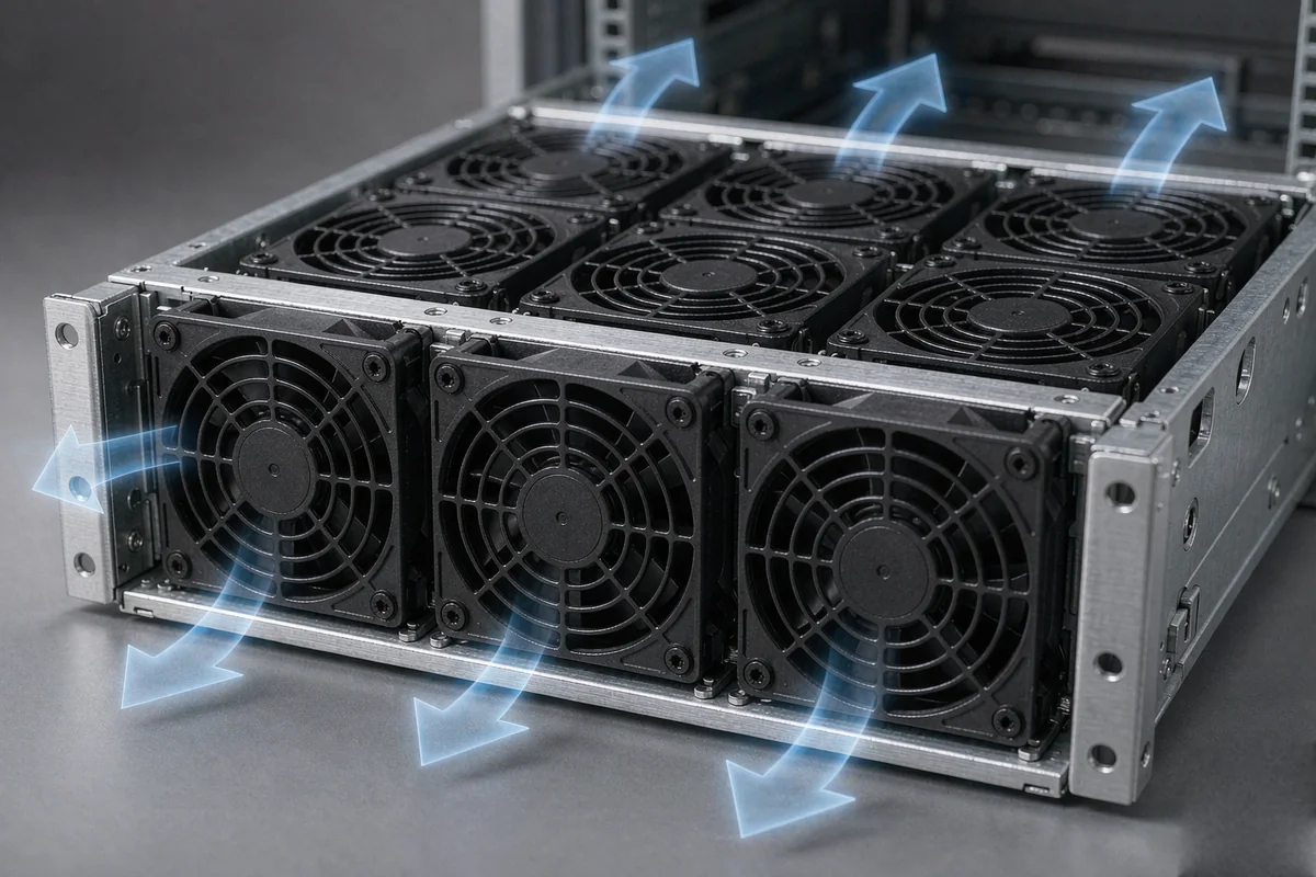
A rack or cabinet fan panel assists air exchange through the enclosure, while every server keeps its own chassis fans and internal airflow path.
| Cooling component | Primary job | Selection focus |
|---|---|---|
| Server chassis fan | Moves air through a specific server enclosure and its heat sinks, memory, drives and accelerator zones. | Chassis impedance, fan module compatibility, PWM and tach feedback. |
| Rack or cabinet fan panel | Assists air exchange through the cabinet when doors, filters or enclosure geometry add resistance. | Total rack heat, opening area, pressure loss, placement and interaction with device fans. |
| Facility cooling system | Delivers conditioned air and removes heat from the room or row. | Supply temperature, airflow management, containment and cooling capacity. |
Adding a cabinet exhaust fan cannot repair a server whose own airflow path is blocked. It can also reduce cooling if it pulls air away from an equipment intake or creates a short path from a nearby opening. Define which level has the problem before adding fan capacity.
Map the rack heat load and inlet conditions
Create a device list with rated or measured power, location in the rack, normal load and peak load. Then measure inlet temperatures at the bottom, middle and top of the rack, because one room sensor can miss a local hot-air recirculation path. Also note which devices change fan speed automatically and whether their exhaust temperature rises during peak workload.
A heat-load calculation can provide an initial airflow estimate, but it is not a final fan size. Actual airflow depends on air density, allowable temperature rise, leakage, bypass, fan interaction and system pressure. Use the estimate to define a test range, then confirm the rack with temperature and pressure measurements.
Match Server Rack Cooling Fans to System Resistance
Free-air CFM is measured with little or no downstream resistance. A working rack is different. Filters, perforated doors, dense drive rows, narrow vents and heat sinks create pressure loss. As resistance rises, the delivered airflow moves along the fan’s pressure-airflow curve, commonly called the P-Q curve.
For an open cabinet with large vents, airflow capacity may be the main constraint. For a filtered or densely packed cabinet, static-pressure capability becomes more important. Compare candidate fans at the expected system resistance rather than comparing only their maximum CFM values.
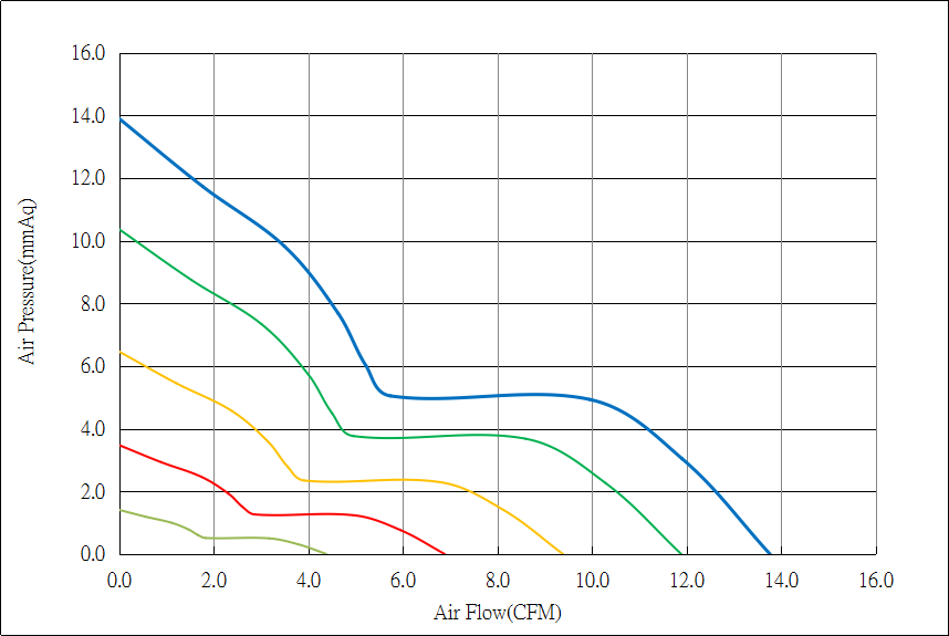
YCCFAN DC4020F P-Q curve: air pressure (mmAq) against air flow (CFM). The airflow actually delivered depends on where the fan curve meets the resistance of the assembled airflow path.
| Rack condition | Likely selection priority | What to verify |
|---|---|---|
| Open rack with clear front-to-rear path | Adequate total airflow at moderate pressure | Uniform inlet temperatures and no hot-exhaust return path |
| Enclosed cabinet with perforated doors | Airflow plus pressure margin | Door open-area ratio and pressure drop |
| Filtered or dust-controlled cabinet | Higher static pressure and maintenance margin | Clean and loaded-filter pressure drop |
| Dense servers, storage or GPU systems | Pressure at the required airflow | Device-specific airflow requirements and thermal throttling |
Where to Place Server Rack Cooling Fans
Fan position should reinforce the direction used by installed equipment. In a front-to-rear rack, additional cabinet fans normally work best when they help admit cool air at the front or remove hot air at the rear without creating a crossflow between the two sides.
- Use rear exhaust assistance only after confirming that the cabinet exhaust path is the bottleneck.
- Avoid placing a strong top or side fan where it steals cool air before that air reaches server inlets.
- Leave clearance around fan inlets and outlets. Guards, grilles and nearby panels can increase pressure loss and noise.
- Seal obvious bypass gaps around shelves or cable openings when they allow air to skip the hot equipment.
- Check airflow direction arrows before installation and after any maintenance change.
Compare the specifications that affect rack cooling
| Field | Why it matters | Selection question |
|---|---|---|
| Dimensions and depth | Determines mechanical fit and available inlet clearance. | Will the fan and guard fit without obstructing cables or service access? |
| Rated voltage and current | Must match the available supply and wiring capacity. | Can the power source support startup and full-speed current? |
| Airflow | Indicates free-air volume, not guaranteed installed airflow. | What airflow is delivered at the expected pressure? |
| Static pressure | Shows ability to overcome restrictive paths. | Is there enough pressure margin for filters, doors and dust loading? |
| P-Q curve | Connects airflow and pressure across the operating range. | Where does the fan intersect the estimated system curve? |
| Noise | High speed and turbulence can make occupied edge sites impractical. | What is the noise at the expected duty, not only at maximum speed? |
| PWM, FG and RD | Enables speed control, tach feedback or fault indication when supported. | Are the voltage levels, frequency and signal definitions compatible with the controller? |
| Bearing and environment | Temperature, dust and continuous duty affect service life. | Are the bearing and rated conditions suitable for the actual site? |
Use YCCFAN specifications as candidate component data
YCCFAN publishes component-level dimensions and performance data that can be used to shortlist fans. Final compatibility still depends on the rack design, power supply, controller and measured operating point.
| Product example | Published data | Potential evaluation use |
|---|---|---|
| DC4020F | 40 × 40 × 20 mm; 5/12/24 V; up to 13.76 CFM and 13.89 mmH2O; optional FG, RD and PWM. | Compact positions needing more pressure than a thinner 40 mm fan, subject to P-Q and integration checks. |
| DC6025G | 60 × 60 × 25 mm; 12/24 V; published variants up to 56.77 CFM and 50.37 mmAq; FG, RD and PWM options listed. | Higher-resistance paths where the 60 mm envelope and acoustic level are acceptable. |
Important: These examples are individual fan components. They are not presented as complete rack-mount cooling trays or as drop-in replacements for proprietary server fan modules.
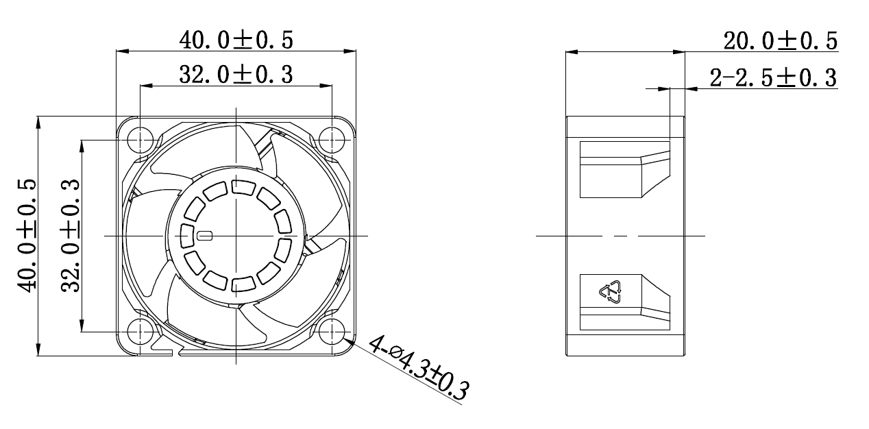
YCCFAN DC4020F dimension drawing: 40.0 ± 0.5 mm frame, 32.0 ± 0.3 mm mounting-hole spacing, 20.0 ± 0.5 mm depth and four Ø4.3 ± 0.3 mm mounting holes.
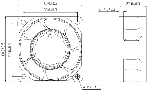
YCCFAN DC6025G dimension drawing: 60.0 ± 0.5 mm frame, 50.0 ± 0.3 mm mounting-hole spacing, 25.0 ± 0.5 mm depth and four Ø4.3 ± 0.3 mm mounting holes.
Control noise without sacrificing thermal margin
Noise is often a result of high rotational speed, turbulent restrictions and multiple fans interacting. Start by removing unnecessary restrictions and recirculation before reducing speed. If the control system supports PWM, use temperature-based control with a defined minimum duty and an alarm response. Verify signal compatibility before connecting a fan to a server BMC or other controller.
Do not judge noise from a free-standing fan alone. A grille, sharp inlet edge, blocked outlet or closely spaced fan panel can change both the sound and the delivered airflow after installation.
Test the Server Rack Cooling System Before Final Selection
A practical validation test should reproduce the highest credible heat load and the least favorable normal condition, such as a warm room, loaded filter or one unavailable fan where redundancy is required.
- Record ambient and server-inlet temperatures at several rack heights.
- Run the representative workload long enough for temperatures and fan speeds to stabilize.
- Record exhaust temperature, device alarms, throttling, fan duty and noise at the operating position.
- Repeat with doors and filters installed, because an open-door test does not represent the final resistance.
- Test the required failure condition if the design depends on fan redundancy.
- Recheck after cable changes, equipment moves or filter loading materially changes the airflow path.
Server rack cooling fan selection checklist
| Check | Confirm before selection |
|---|---|
| Airflow direction | All major devices use a compatible direction and the cabinet supports that path. |
| Heat load | Normal and peak device power or measured thermal behavior is documented. |
| Restrictions | Doors, filters, grilles, cables, blanks and ducts are included in the assessment. |
| Operating point | Candidate P-Q data covers the required airflow at the expected pressure. |
| Mechanical fit | Frame size, depth, mounting, guards and service clearance are confirmed. |
| Electrical fit | Voltage, current, connector and wiring capacity are confirmed. |
| Control signals | PWM, FG or RD requirements and signal definitions are verified. |
| Failure response | Alarm, redundancy and safe operating behavior are defined where required. |
| Validation | Temperatures, fan duty, alarms and noise pass under representative load. |
Frequently asked questions
Should server rack cooling fans be intake or exhaust fans?
The answer depends on the rack airflow design. In a typical front-to-rear arrangement, cabinet fans should reinforce that route. Rear exhaust assistance may help an enclosed cabinet, but it should not create negative pressure that starves server inlets. Confirm the effect with inlet-temperature and airflow measurements.
Is higher CFM always better for server cabinet cooling?
No. Maximum CFM is a free-air rating. A restrictive rack can move less air than expected if the fan lacks static-pressure capability. Compare the P-Q curve at the expected system resistance and validate the installed result.
Can one cabinet fan cool every server in a rack?
Not necessarily. Each server has its own airflow path and internal fans. A cabinet fan can assist air exchange, but it cannot guarantee uniform flow through every device. Rack layout, blanking, cable routing and device-level requirements still need to be checked.
How often should rack cooling airflow be checked?
Check after installation and after material changes such as adding equipment, moving cables, replacing doors or filters, changing fan control settings or observing higher inlet temperatures. Sites with dust filters should also inspect pressure loss and temperature trends as filters load.
Get fan selection support
To shortlist a YCCFAN component, provide the required fan dimensions, rated voltage, estimated airflow and static pressure, P-Q operating point, controller signals, inlet temperature, mounting position, noise limit and expected operating hours. If the system curve is not available, provide drawings and details of doors, filters, grilles, cable paths and internal obstructions so the assumptions can be reviewed before sampling.
Contact YCCFAN for component selection support, or browse the YCCFAN DC fan range to compare chassis-level fan options.